
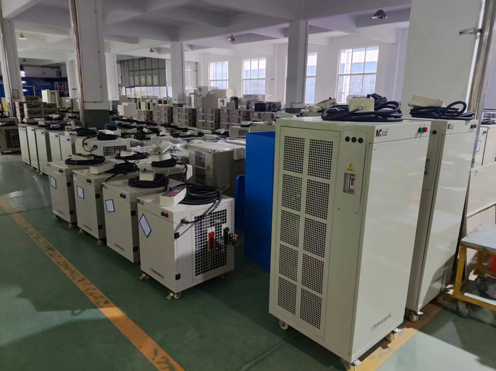
The rectifier is the heart of an electroplating line: it converts incoming AC mains power into the controlled DC current that actually deposits metal onto the part. Get the rectifier wrong — undersized, poorly regulated, or the wrong technology for your process — and you get inconsistent deposit thickness, poor adhesion, and wasted chemistry, no matter how well the rest of the line is designed. This guide covers how to choose the right rectifier for a plating, anodizing, or electropolishing line.
1. What the Rectifier Actually Controls
A plating rectifier does two jobs: it converts AC to DC, and it regulates that DC output precisely enough to control the plating reaction. Regulation quality directly affects deposit thickness uniformity, grain structure, and coverage in recessed areas — so the rectifier is not just a power source, it is a process control instrument.
2. Rectifier Technologies: SCR, IGBT, and Switch-Mode
SCR (thyristor) rectifiers
The traditional technology for higher-current plating lines. SCR rectifiers are robust and cost-effective at high current, but phase-angle control produces higher output ripple and lower efficiency than newer designs, and their response to load changes is slower.
IGBT (high-frequency switch-mode) rectifiers
IGBT rectifiers switch at high frequency, which allows a much smaller transformer, higher efficiency (commonly 90%+ versus 80–85% for SCR types), lower output ripple, and faster dynamic response — important for pulse and pulse-reverse plating. They have become the standard choice for new plating and anodizing lines across most current ranges, which is why Asia Greenhub’s electroplating rectifiers are built on IGBT platforms.
Switch-mode (high-frequency) rectifiers, generally
This is the broader category IGBT designs fall under. Compared with older SCR units, high-frequency switch-mode rectifiers are smaller and lighter for the same output rating, run cooler, and hold their set point more precisely under load fluctuation — a meaningful advantage in lines where multiple tanks share one mains supply.
3. Key Selection Parameters
- Output current and voltage range: sized to your tank’s largest expected load (total part surface area × required current density), with margin for future capacity.
- Ripple: lower ripple (typically under 5%, and often under 1% on modern IGBT units) gives smoother, more uniform deposits, particularly important for bright nickel, gold, and other decorative or functional coatings sensitive to current quality.
- Control mode: constant current (CC) for consistent deposit thickness regardless of resistance changes, constant voltage (CV) for some anodizing processes, and pulse or pulse-reverse capability where the process calls for it (see below).
- Duty cycle and cooling: confirm the rectifier is rated for continuous duty at your required output, not just a short-term peak rating, and choose air- or water-cooling based on ambient conditions and enclosure space.
- Certifications: CE certification and documented compliance with relevant electrical safety standards matter for insurance, export, and integration into a wider automated line.
4. Sizing a Rectifier: A Practical Method
Start from current density (A/dm² or A/ft²), which is specific to your plating chemistry and process (consult your chemical supplier’s process data sheet). Multiply by the total surface area of parts being plated simultaneously to get required current. Add margin — commonly 20–30% — to cover rack losses, busbar drop, and future capacity, then select the next standard rectifier rating at or above that figure. Undersizing forces the rectifier to run continuously at its ceiling, shortening its service life and limiting your ability to run larger batches later.
5. Pulse and Pulse-Reverse Plating
Pulse plating switches the current on and off at controlled intervals rather than running continuous DC, which can improve deposit uniformity, reduce porosity, and allow higher effective current density without burning. Pulse-reverse plating periodically reverses polarity for a short interval, which is used to improve throwing power into recesses and through-holes and to produce finer grain structure in some chemistries. Not every process benefits from pulse plating — it adds rectifier cost and complexity — but for high-value or high-precision plating (connectors, PCB through-hole, aerospace components) it is often worth the investment. Confirm with your rectifier supplier whether pulse and pulse-reverse modes are built in or require an add-on module.
6. Common Failure Points and Maintenance
The most common causes of rectifier problems in the field are undersized busbar or cabling causing overheating at connections, inadequate cooling airflow (for air-cooled units) allowing internal temperatures to creep up over time, and contactor or connection corrosion in humid, chemically aggressive plant environments. Keep connection points clean and torqued to specification, verify cooling fan or water-cooling operation on a routine schedule, and monitor output ripple periodically — a rising ripple reading is often the first sign of an ageing rectifier component before an outright failure.
Frequently Asked Questions
IGBT or SCR — which is better for my line?
For most new installations, IGBT (high-frequency switch-mode) rectifiers are the better choice: higher efficiency, lower ripple, smaller footprint, and faster response. SCR rectifiers remain a reasonable choice mainly where an existing line is being extended with matching equipment, or at very high current ratings where switch-mode cost premiums are largest.
How much current do I actually need?
Calculate it from your process’s required current density multiplied by the total part surface area you plan to plate simultaneously, then add roughly 20–30% margin for losses and future growth. Your plating chemistry supplier can provide the current density figure for your specific process.
Do I need pulse plating capability?
Only if your process specifically calls for it — typically precision, high-value, or geometrically complex parts. Standard barrel or rack plating of simpler parts usually runs well on constant current DC.
What ripple level should I look for?
Under 5% is generally acceptable for most plating processes; under 1–2% is preferred for bright, decorative, or precision deposits where surface finish quality is critical.
Need Help Sizing an Electroplating Rectifier?
Asia Greenhub supplies CE-certified IGBT electroplating rectifiers sized to your current, voltage, and control requirements, alongside the PP tanks and filtration systems that make up the rest of a plating line. Send us your current density, part surface area, and process type and we will recommend a suitable rectifier configuration.
Leave a Reply